
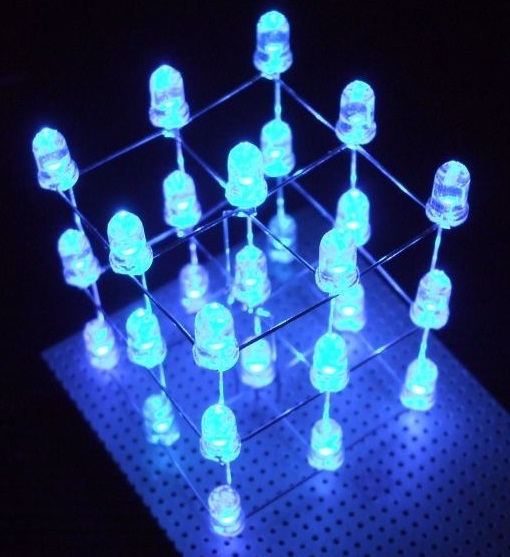
3×3 LED Cube
The Process…
click to enlarge
To make the cube you will work through the following steps:
- Building the LED cube matrix
- Breadboarding the circuit
- Creating a PCB
- Making a project enclosure
- Assembling the final project
- Programming the cube
Credit: this project took inspiration from the following this instructable by gzip.
1. Building the LED Matrix

click to enlarge
To build the matrix, each layer, comprised of 9 LEDs, will be built and tested, then the layers will be combined to form three levels.
You will need to gather the following items:
- soldering ‘jig’ (board with holes in it)
- 27 LEDs
- Soldering tools and materials (including eye protection)
- Alligator clips
Complete the steps detailed in the document below…
2. Breadboarding The Circuit
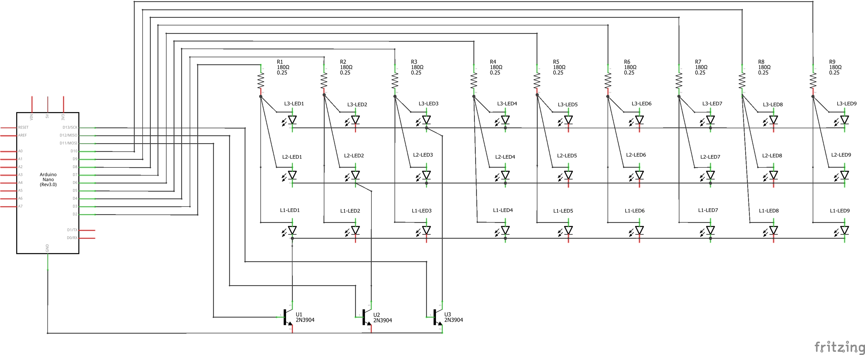
click to enlarge
- Use the provided schematic to breadboard your circuit
- Need to make the image bigger? Right click on the image and select ‘Open image in new tab’. Then select that tab. Now, press the ‘Ctrl’ key and scroll your mouse wheel while hovering over the image.
- Have your teacher look over your work BEFORE connecting the USB to the Nano
- Use the Arduino IDE to upload the provided ‘sketch’. You will find this inside the following zipped folder, along with other resources. In order for the sketch to upload, you will need to install the included library.
ledcube (compressed ‘zip’ folder)
- Hopefully you now have a working LED Matrix! If not, remove the USB cable and carefully look over your breadboarding work.
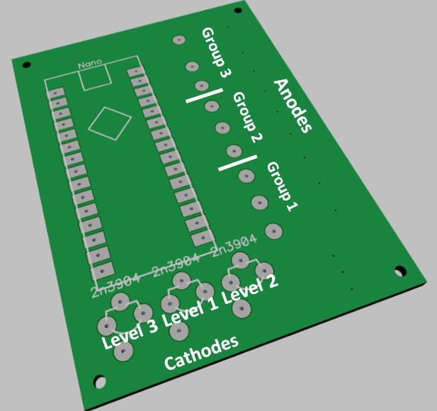
3. Making the Circuit Board
- ‘Import’ the following file linked below into the laser’s UCP.
- Use the ‘three pass process’ and the following ‘manual’ settings to engrave a circuit board.
- 1st pass – 40 power, 100 speed, 300 PPI
- 2nd & 3rd passes – 100 power, 40 speed, 800 PPI
4. Designing and Making the Enclosure
- Download the model files lined below. Open the zipped folder, then copy and paste the model file within to your project location (should be in OneDrive)
- Open the app Tinkerine Suite, check all settings, then slice and print
5. Final Project Assembly
- How to make the resistor plate assembly
- PCB wiring
- solder in ‘header pins’ to form a socket that will receive the Nano
- Solder in three NPN 3904 transistors (flat face towards header pins)
- Solder stranded wire (red) to all Anode pads and lace through appropriate holes
- compare wire length to sample (too long is bad, too short is bad)
- Solder stranded wire (black) to all Cathode pins
- again, wire length is important, check sample
- Attaching the PCB to the Resistor Plate / LED Array
- connections need to be kept as short as possible to prevent the folding over of these during assembly which could lead to short circuits!
- Working from left to right, or from right to left, on the circuit board, attach the ‘group’ of three anode wires to a row of resistors on the resistor plate
- Attach the next group of three anode wires to the next row of resistors on the anode plate
- Finally, attach the remaining group of anode wires to the remaining resistor row.
- Lastly, attach the cathode wires from the PCB to the cathode wires on the resistor plate
Supporting Images
Click image to enlarge
6. Programming Your Project
FOLLOW THIS GUIDE to work your way through the programming process to get up and running with your cube!