
CAD Assignment #4 – Caster Spacer
This assignment will teach you how to create an accurate model of an object (a swivel caster mounting plate) working from a 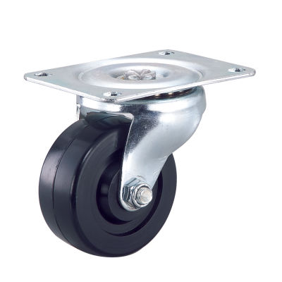 picture/image of the object.
Tutorial 1 – Importing an image file to a ‘Canvas’ and calibrating
- (you will need this image file)
- Caster Reference Pics (measurements)
Step 3 – Laser Cut The Template (no video, follow the steps below)
- Create a drawing (use 11″ x 81/2″ paper size)
- only place one view (top view)
- scale 1:1
- ‘Output’ the drawing in PDF format to your drafting 10 folder in your ‘Documents’
- Open Inkscape
- ‘import’ (under the file tab) your pdf into Inkscape (accept defaults)
- Use ‘Fill and Stroke’ (under Object) to change the line types to
- all red (255 on the RGB spectrum)
- 0.001 inch thickness
- Use ‘save a copy’ (under the file menu) to save a ‘PDF’ file version that includes your new line type setings
- Use ‘File Explorer’ on your computer to locate your pdf file. ‘Right Click’ on the file and select ‘Open with’ – Adobe Reader
- From Adobe Reader, ‘print’ your file to the Laser’s User Control Panel (select ‘VL4.60/75’ from the print list)
- Open the Laser User Control Panel (UCP) and you should see your drawing and the all lines should be red
- At the laser, use the ‘how to guide’ to complete the steps required to cut your template.
- Test your template against the caster for accuracy
Step 4 – Make adjustment based on fit – no video
- make adjustments to your sketch based on what you believe is need after checking your first template against th caster. Grading will be determined by how close your fit is to the actual object.
Step 5 – Creating a drawing – no video
- Using your existing knowledge from previous assignments, create a dimensioned orthographic style drawing of your caster mounting plate spacer. Consider the following
- Select a paper size and drawing scale that will maximize clarity
- Place all dimensions on the Top View, except for the spacer’s thickness
- Slots should show radius of arc at end and location of ‘center’ points for drilling each end. If your slots are NOT located the same at each corner you will need to dimension all slot locations.
- Remember all information to manufacture the part must be included, but no unnecessary information should be added.
Sample drawing for reference (your dimensions will differ slighlty based on how you traced the image): Caster Spacer Drawing